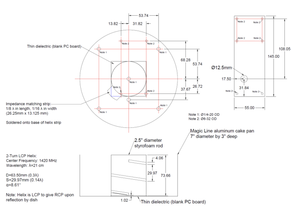
Technical Schematic of MIT SRT Helical Feed System
Engineering diagram of the two-turn helical feed for 1.42 GHz hydrogen line observations.
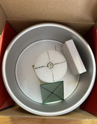
Assembled Helical Feed System in Reflector
Top view of the helical feed mounted in the aluminum reflector pan.
The design illustrated in the MIT Small Radio Telescope (SRT) feed system represents a sophisticated and well-tuned helical antenna optimized for radio frequency (RF) reception at the hydrogen line (21 cm wavelength or 1.42 GHz), which is a critical frequency in radio astronomy for observing interstellar hydrogen. Let us deconstruct and explore the design elements of this feed system with scientific rigor.
1. Helical Antenna Design
The primary radiative component of this setup is a two-turn helical antenna, fabricated from a low-cost printed circuit board (PCB) material and structured into a two-turn helical configuration. Here are some key technical specifications and rationales behind this helical design:
Frequency of Operation: The helical feed is precisely tuned to a center frequency of 1420 MHz, correlating to a free-space wavelength of approximately 21 cm. This frequency corresponds to the emission line of neutral hydrogen (HI), a fundamental spectral line in radio astronomy that enables mapping of galactic and extragalactic hydrogen distributions.
Helix Dimensions and Geometry: The diameter of the helix, approximately 63.5 mm, is selected based on the wavelength of operation (λ). Helical antennas operating in axial mode typically have diameters around 0.3λ, balancing gain and beamwidth for optimal sensitivity in the SRT system. The pitch (or axial separation between turns) is selected to support a single polarization mode, thus ensuring circular polarization characteristics suitable for astronomical observations.
Impedance and Feed Matching: The feed includes a quarter-wavelength impedance matching strip with dimensions carefully calculated to ensure minimal reflection (i.e., optimized voltage standing wave ratio, or VSWR) at the feed point. This strip is approximately 1/16 inch in width and 1/8λ in length, intended to match the impedance of the helical antenna to the input impedance of the receiving system, which is typically 50 ohms. This minimizes signal loss and maximizes power transfer from the antenna to the receiver.
Polarization Characteristics: The helix’s direction of winding, specified as Left-Hand Circular Polarization (LHCP), is crucial because it ensures Right-Hand Circular Polarization (RHCP) upon reflection from the parabolic dish reflector. This polarization selection is not arbitrary; RHCP is preferred in astronomical applications to maximize sensitivity to right-hand circularly polarized emissions, which are commonly observed in natural astronomical phenomena.
2. Reflector Assembly
The helical antenna is centrally mounted within a circular aluminum reflector structure, specified as a "Magic Line" aluminum cake pan with a diameter of 7 inches and a depth of 3 inches. This reflector serves multiple critical roles in the feed system:
Directivity and Gain Enhancement: The reflector effectively captures and focuses the incoming electromagnetic waves, reflecting them onto the helical feed for optimal signal reception. The choice of a 7-inch diameter enhances the gain of the system by providing a sufficiently large aperture for capturing incident waves without introducing excessive side lobes, thus improving the antenna’s sensitivity.
Surface Material and Conductivity: Aluminum is chosen for its high electrical conductivity and low mass, minimizing resistance losses at the RF range while also keeping the structure lightweight for practical mounting on the telescope.
Structural Simplicity and Stability: The circular pan structure provides a stable mounting surface and is compatible with the axial alignment of the helical feed. This design is both structurally efficient and cost-effective, contributing to the practicality of the system.
3. Dielectric and Support Structures
The dielectric components in the feed system, including a blank PCB board and a styrofoam rod, are integral to the antenna’s stability and performance:
Styrofoam Rod for Structural Support: A 2.5-inch diameter styrofoam rod supports the helical antenna within the reflector, maintaining precise alignment with respect to the parabolic reflector’s focal point. Styrofoam is chosen for its low dielectric constant and minimal RF absorption properties, ensuring it does not interfere with the antenna's electromagnetic performance.
PCB Dielectric Layers: The thin dielectric layers (blank PCB boards) serve as mounting substrates for the impedance matching strip and possibly for maintaining the physical integrity of the helical windings. The choice of PCB is strategic due to its rigidity, availability, and low-loss tangent at microwave frequencies, ensuring minimal signal attenuation and phase distortion.
4. Mechanical Assembly and Mounting
The entire feed assembly, including the helix, reflector, dielectric elements, and impedance matching strip, is designed with precise mechanical tolerances, as evident from the detailed engineering diagram. Specific notes, such as thread sizes (e.g., 1/4-20 and 8-32), indicate standardized connections, allowing easy attachment to the main telescope structure.
5. Electromagnetic Performance Analysis
Axial Mode Operation: The two-turn helical configuration is optimized to operate in axial mode, providing a well-defined, directional radiation pattern along the axis of the helix. This pattern is essential for maximizing sensitivity in the direction of the telescope’s field of view.
Beamwidth and Gain Considerations: Given the diameter and spacing of the helix, the antenna achieves a narrow beamwidth with high gain, focusing the reception within a confined solid angle. This enhances sensitivity to distant radio sources while mitigating interference from off-axis noise sources.
Circular Polarization and Reflection Symmetry: The RHCP upon reflection is critical for consistency in observational data. By ensuring a circular polarization upon reflection, the system can more accurately measure polarized astronomical emissions, which can be indicative of magnetic fields and other astrophysical phenomena in observed regions.